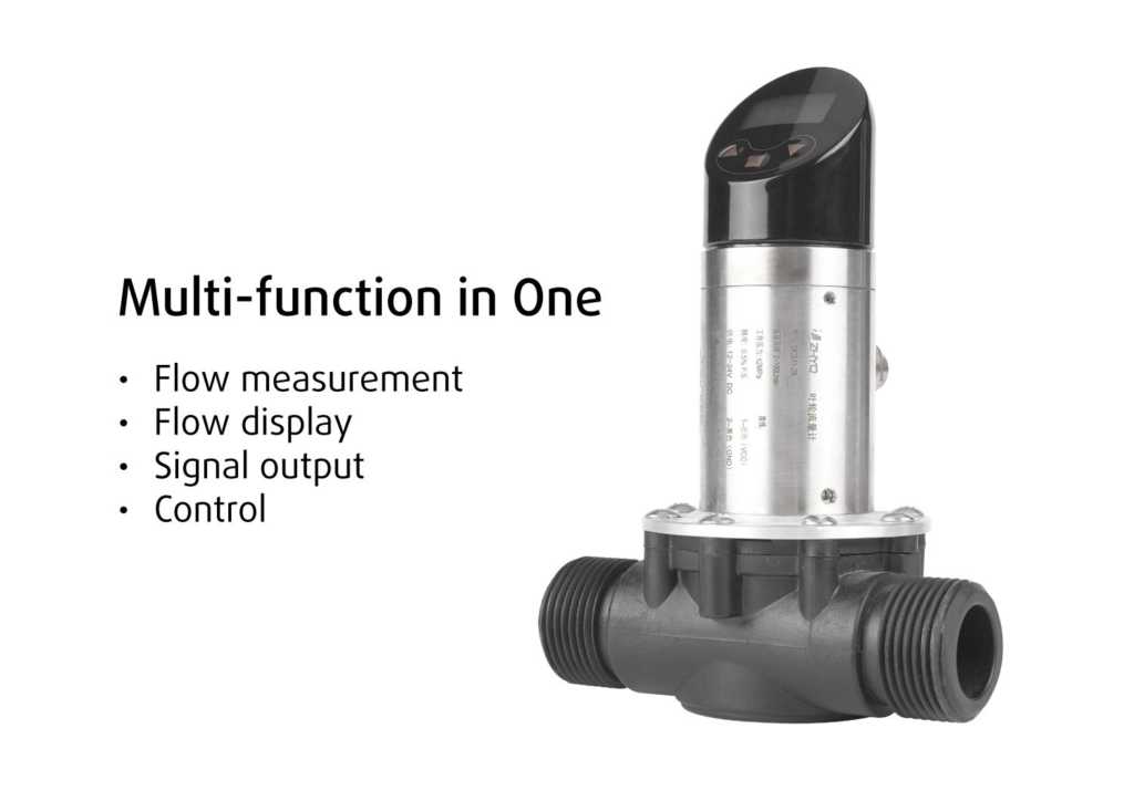
I. Descriptions
The impeller flowmeter is an intelligent digital flow measurement and control product that integrates flow
measurement, display, output and control. The product is an impeller body and an electronic structure. The output
pulse signal is processed by a high-precision, high-speed, low-latency microprocessor. The velocity, flow, pressure,
pipe diameter, and pulse relationship are calculated by calibration, and the generated flow can be calculated by the
number of pulses. The signal processed by calculation is remotely monitored and controlled to measure and control
the system flow. It is flexible to use, simple to operate, easy to debug, safe and reliable. It is widely used in
hydropower, tap water, petroleum, chemical industry, mechanical equipment, hydraulic lubrication and other
industries to measure, display and control the flow of fluid media.
II . Application
Various liquids, gases, etc.
Petrochemical, environmental protection, pharmaceuticals
Water treatment, food processing, etc.
III . Feature
Small size, high precision, fast response
Easy to install, wide measuring range
High reliability, reasonable price
OLED indicator can be rotated 270
IV. Working principal
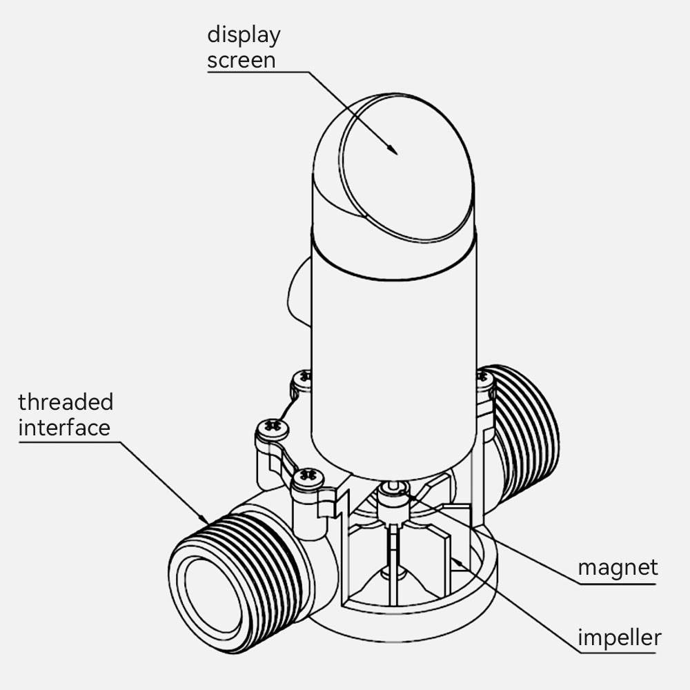
The key components of the impeller flowmeter are the impeller, a magnet and a Hall element. The impeller flowmeter is installed in the pipeline. When the fluid flows through the impeller flowmeter through the pipeline, the impeller will rotate. The speed of the impeller rotation is proportional to the flow velocity in the fluid. When the flow velocity increases, the impeller rotates faster; when the flow velocity decreases, the impeller rotates slower. At the same time, the sensor detects the magnet or Hall element on the impeller, thereby generating an electrical signal. The electrical signal will change with the speed of the impeller. By measuring the speed of the impeller, the flow velocity of the fluid is measured, and then the flow rate of the fluid is determined.
V. Structure and Drawing
VI. Specification
| Range | 2-100L/min |
| Accuracy | 0.5% |
| Power supply | 12-24V |
| Pipe inner diameter | 20mm |
| Pipe pressure | ≤ 2.0MPa |
| Working temperature | -20~85℃ |
| Output | 4-20mA (3wires) |
| Electric connector | 5spins |
| Process connection | G1, other |
| Display method | OLED |
VII. Wiring Definition

| Pin | Cable color | Function |
| Pin1 | Red | VCC |
| Pin2 | Black | GND |
| Pin3 | Blue | NC |
| Pin4 | Yellow | 4-20mA |
| Pin5 | White | NC |